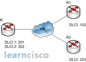
Let’s get started by looking at a simple example given on the folllowing scheme from the previous page:

Here are how these configurations would look about all of the routers:
Router R1:
!

interface Serial1/0

ip address 192.168.1.1 255.255.255.0

encapsulation frame-relay

frame-relay interface-dlci 102

frame-relay lmi-type ansi

!
…
!
ip classless
ip route 0.0.0.0 0.0.0.0 192.168.1.254
!
Router R2:
!

interface Serial1/0

ip address 192.168.2.2 255.255.255.0

encapsulation frame-relay

frame-relay interface-dlci 203

frame-relay lmi-type ansi

!
…
!
ip classless
ip route 0.0.0.0 0.0.0.0 192.168.2.254
!
Router R:
!

interface Serial1/0

no ip address

encapsulation frame-relay

frame-relay lmi-type ansi

!

interface Serial1/0.201 point-to-point

ip address 192.168.1.254 255.255.255.0

frame-relay interface-dlci 201

!

interface Serial1/0.302 point-to-point

ip address 192.168.2.254 255.255.255.0

frame-relay interface-dlci 302

!
Concentrate on the configuration of the Router R1. The first step is to specify the encapsulation as Frame Relay. Notice that since I didn’t specify a particular encapsulation type-either Cisco or IETF-the Cisco default type was used. If the other router were non-Cisco, I would’ve specified IETF. Next, I assigned an IP address to the interface, then specified the LMI type of ANSI (the default being Cisco) based on information provided by the telecommunications provider. Finally, I added the DLCI of 102, which indicates the PVC we want to use (again, given to me by my ISP) and assumes there’s only one PVC on this physical interface. That’s all there is to it-if both sides are configured correctly, the circuit will come up.
Subinterfaces
You probably know by now that we can have multiple virtual circuits on a single serial interface and yet treat each as a separate interface. We can make this happen by creating subinterfaces. Think of a subinterface as a logical interface defined by the IOS software. Several subinterfaces will share a single hardware interface, yet for configuration purposes they operate as if they were separate physical interfaces, something known as multiplexing. To configure a router in a Frame Relay network so it will avoid split horizon issues by not permitting routing updates, just configure a separate subinterface for each PVC, with a unique DLCI and subnet assigned to the subinterface.
You define subinterfaces using a command like int s0.subinterface number. First, you have to set the encapsulation on the physical serial interface, and then you can define the subinterfaces- generally one subinterface per PVC. You can define a serious amount of subinterfaces on any given physical interface, but keep in mind that there are only about a thousand available DLCIs. Take a look on the Router R configuration. It is exactly the mentioned example.
Multipoint – This is when the router is the center of a star of virtual circuits that are using a single subnet for all routers’ serial interfaces connected to the frame switch. You’ll usually find this implemented with the hub router in this mode and the spoke routers in physical interface (always point-to-point) or point-to-point subinterface mode.
Our Recommended Premium CCNA Training Resources
These are the best CCNA training resources online:
Click Here to get the Cisco CCNA Gold Bootcamp, the most comprehensive and highest rated CCNA course online with a 4.8 star rating from over 30,000 public reviews. I recommend this as your primary study source to learn all the topics on the exam.

Want to take your practice tests to the next level? AlphaPreps purpose-built Cisco test engine has the largest question bank, adaptive questions, and advanced reporting which tells you exactly when you are ready to pass the real exam. Click here for your free trial.
