STP’s main task is to stop network loops from occurring on your layer 2 network (bridges or switches). It vigilantly monitors the network to find all links, making sure that no loops occur by shutting down any redundant links. STP uses the spanning-tree algorithm (STA) to first create a topology database, then search out and destroy redundant links. With STP running, frames will be forwarded only on the premium, STP-picked links.
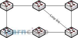
The Spanning-Tree protocol is necessary in networks as these.

In the picture above we have a switched network with a redundant topology (switching loops). Without some type of layer 2 mechanism to stop the network loop, we would have the problems we discussed previously: broadcast storms and multiple frame copies.
Terms
- STP – STP is a bridge protocol that uses the STA to find redundant links dynamically and create a spanning-tree topology database. Bridges exchange BPDU messages with other bridges to detect loops, and then remove them by shutting down selected bridge interfaces.
- Root bridge – The root bridge is the bridge with the best bridge ID. With STP, the key is for all the switches in the network to elect a root bridge that becomes the focal point in the network. All other decisions in the network-such as which port is to be blocked and which port is to be put in forwarding mode-are made from the perspective of this root bridge.
- BPDU – All the switches exchange information to use in the selection of the root switch, as well as in subsequent configuration of the network. Each switch compares the parameters in the Bridge Protocol Data Unit (BPDU) that they send to one neighbor with the one that they receive from another neighbor.
- Bridge ID – The bridge ID is how STP keeps track of all the switches in the network. It is determined by a combination of the bridge priority (32,768 by default on all Cisco switches) and the base MAC address. The bridge with the lowest bridge ID becomes the root bridge in the network.
- Nonroot bridge – These are all bridges that are not the root bridge. Nonroot bridges exchange BPDUs with all bridges and update the STP topology database on all switches, preventing loops and providing a measure of defense against link failures.
- Root port – The root port is always the link directly connected to the root bridge, or the shortest path to the root bridge. If more than one link connects to the root bridge, then a port cost is determined by checking the bandwidth of each link. The lowest-cost port becomes the root port. If multiple links have the same cost, the bridge with the lower advertising bridge ID is used. Since multiple links can be from the same device, the lowest port number will be used.
- Designated port – A designated port is one that has been determined as having the best (lowest) cost. A designated port will be marked as a forwarding port.
- Port cost – Port cost determines when multiple links are used between two switches and none are root ports. The cost of a link is determined by the bandwidth of a link.
- Nondesignated port – A nondesignated port is one with a higher cost than the designated port. Nondesignated ports are put in blocking mode-they are not forwarding ports.
- Forwarding port – A forwarding port forwards frames.
- Blocked port – A blocked port is the port that will not forward frames, in order to prevent loops. However, a blocked port will always listen to frames.
The bridge ID is used to elect the root bridge in the STP domain as well as to determine the root port for each of the remaining devices in the STP domain. This ID is 8 bytes long, and includes both the priority and the MAC address of the device. The default priority on all devices running the IEEE STP version is 32,768.
To determine the root bridge, the priority of each bridge is combined with its MAC address. If two switches or bridges happen to have the same priority value, then the MAC address becomes the tiebreaker for figuring out which one has the lowest (best) ID. It’s like this: If two switches-I’ll name them A and B-both use the default priority of 32,768, then the MAC address will be used instead. If Switch A’s MAC address is 0000.0c00.1111 and Switch B’s MAC address is 0000.0c00.2222, then Switch A would become the root bridge. Just remember that the lower value is the better one when it comes to electing a root bridge.
BPDUs are sent every two seconds, by default, out all active ports on a bridge/switch, and the bridge with the lowest (best) bridge ID is elected the root bridge. You can change the bridge’s ID by lowering its priority so that it will become a root bridge automatically. Being able to do that is important in a large switched network-it ensures that the best paths are chosen. Changing the default priority is the best way to choose a root bridge. This is important, since you want your core switch in your network to be your root bridge so STP will converge quickly. Even though the commands for configuring the switches are covered later in this chapter, it is necessary to show you the configurations now to help explain the priority concept, which is very important for your studies.
If more than one link leads to the root bridge, then cumulative outbound port costs along the path to the root bridge becomes the factor used to determine which port will be the root port for that device. So, to determine the port that will be used to communicate with the root bridge, you must first figure out the path’s cost. The STP cost is an accumulated total path cost based on the rated bandwidth of each of the links. This information is then used internally to select the root port for that device, and this value will be advertised in BPDUs out each interface of the device. The neighbor switches compare these values to its own root cost to determine which of them will have the designated port for the link between them. Table 7.1 shows the typical costs associated with various Ethernet networks.
| Speed | New IEEE Cost | Original IEEE Cost |
|---|---|---|
| 10 Gbps | 2 | 1 |
| 1 Gbps | 4 | 1 |
| 100 Mbps | 19 | 100 |
| 10 Mbps | 100 | 100 |
The IEEE 802.1D specification has recently been revised to handle the new higher-speed links. The IEEE 802.1D specification assigns a default port cost value to each port based on bandwidth.
The ports on a bridge or switch running STP can transition through five different states:
- Blocking – A blocked port won’t forward frames; it just listens to BPDUs. The purpose of the blocking state is to prevent the use of looped paths. All ports are in blocking state by default when the switch is powered up.
- Listening – The port listens to BPDUs to make sure no loops occur on the network before passing data frames. A port in listening state prepares to forward data frames without populating the MAC address table.
- Learning – The switch port listens to BPDUs and learns all the paths in the switched network. A port in learning state populates the MAC address table but doesn’t forward data frames.
- Forwarding – The port sends and receives all data frames on the bridged port. If the port is still a designated or root port at the end of the learning state, it enters this state.
- Disabled – A port in the disabled state (administratively) does not participate in the frame forwarding or STP. A port in the disabled state is virtually nonoperational.
Our Recommended Premium CCNA Training Resources
These are the best CCNA training resources online:
Click Here to get the Cisco CCNA Gold Bootcamp, the most comprehensive and highest rated CCNA course online with a 4.8 star rating from over 30,000 public reviews. I recommend this as your primary study source to learn all the topics on the exam.

Want to take your practice tests to the next level? AlphaPreps purpose-built Cisco test engine has the largest question bank, adaptive questions, and advanced reporting which tells you exactly when you are ready to pass the real exam. Click here for your free trial.
