We will explain some examples like the public switched telephone network and common connectivity options like point-to-point connections, leased lines, and various encapsulation methods for that type of connectivity. The lesson ends with a brief description of other layer 2 options like frame relay and ATM.
Circuit Switching
Circuit switching options used to rule the world of wide area networks. Back in the day of asynchronous serial interfaces with low bandwidth, those were the options of choice for wide area connectivity. Later options like ISDN would not only represent backup dial-on-demand type connectivity but also the main connectivity for central offices.
Under those options, a dedicated path was established and maintained and in fact terminated through a carrier network for each communication session. The different options would use different encapsulation methods and so you could use PPP encapsulation on top of an ISDN transport or HDLC and/or PPP in asynchronous serial options.
Public Switched Telephone Network
The most common type of circuit switch to WAN is the PSTN, also referred to as the plain old telephone service or POTS, typically used for voice transport. PSTN was also used as a data transport network back in the day when the upper limit of around 33 Kb/s was actually considered good. Jumping to 56 Kb/s through digital connections was a big boom.
Even though PSTN is still low cost, highly available and relatively simple to configure and maintain, the low data rates provided by PSTN probably make it a non-option for the broadband requirements and high speed connectivity of today’s networks.
Leased Lines using TDM Technology
Other options that would eventually use a serial interface were lease lines using TDM (Time Division Multiplexing) technology. These were dedicated point-to-point services even though they would use multiplexing technologies within the service provider network, but still point-to-point and dedicated private networks nonetheless.
The underlying network is based on T-carrier or E-carrier technologies and the typical components were a DTE and a DCE in the form of CSU/DSU. We know what the disadvantages of these were and are. Cost is high and pricing is based on bandwidth – the more bandwidth, the more expensive.
WAN Connection Bandwidth
TDM networks will define the underlying physical technologies, but they also define the naming conventions for bandwidth parameters, so DS0 was the building block with 64 Kb/s. This was also the bandwidth required for an uncompressed digitized phone call using pulse code modulation. Well, a bundle of DS0s would become a DS1, which is the bandwidth associated with a T1 line (1.544 Mb/s).
This is true in the United States, but different in other countries. For example, European standards would use different bandwidths and frame structures in their E1s. So a bundle of 24 DS0s would be a DS1; sometimes used interchangeably with the term T1. Twenty-eight DS1s would be bundled to get a DS3 line, also referred to sometimes as T3 with speed and bandwidth of 43.736 Mb/s.
Configuring a Serial Interface
All of these options could use serial interfaces, so let us take a look at the configuration commands to set up and initialize a serial interface. You would have to go into global configuration mode and then enter interface configuration mode for the serial interface. The clock rate command would only apply if the cable connected to the router was a DCE or data communications equipment. In that case, the router side would have to provide clocking, and so you use a clock rate command to define clocking.
Router#conf t
Router(config)#
Router(config)#interface serial 0/0/0
Router(config-if)#
Router(config-if)#clock rate 64000
Router(config-if)#bandwidth 64
Router(config-if)#exit
Router(config)#exit
Router#
In real life, typically the DCE device, a CSU/DSU, would provide clocking and so you would not need this in a router. It does make sense though in routers connected back to back where one of them has to provide clocking. The clock rate command deals with the actual physical clocking and speed and bit rate. However, the bandwidth command deals with the bandwidth label used by routing protocols to determine the cost of going through this interface. It is also used for quality of service (QoS) and available bandwidth calculations at the interface level. It is important to set the bandwidth to the actual bandwidth because if not, serial interfaces default to DS1 speed.
In order to determine the type of cable connected to the router, whether DTE or DCE, you could use a show controller command with reference to the specific interface and you will see in the first couple of lines the type of cable like that.
Router#show controller serial 0/0/0
HD unit 0, idb = 0x121C04, driver structure at 0x127078
buffer size 1524 HD unit 0, V.35 DTE cable
Point-to-Point considerations
Point-to-point links have been the traditional connection of choice. They are simple to configure and install, require minimal expertise and because they were typically a dedicated connection, they would suffer from minimal latency and jitter and offer a higher quality of service. Their dedicated capacity meant that there was high availability for critical traffic. The disadvantage is as usual and has always been cost, also limited flexibility in terms of growing and scaling to more bandwidth and more services.
HDLC and Cisco HDLC
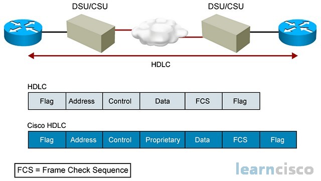
One of the options to encapsulate traffic across the serial connection is HDLC (High-Level Data Link Control). Although supporting point-to-point and multipoint configurations, HDLC and its Cisco implementation is the default encapsulation for serial lines and only point-to-point connections are allowed. There are no windowing or forward flow control capabilities on the Cisco implementation of HDLC and there are proprietary extensions to the protocol, as you can see in the frame format down there. Because of this, there is no interoperability with other HDLC implementations from other vendors.

Configuring HDLC is fairly simple. Simply going to the interface and with the encapsulation command set it to HDLC.
Router(config-if)#encapsulation hdlc
This is going to be the default though on serial interfaces, so you do not have to do this. But if you want to set it back to HDLC after configuring something else, then you can use this command. The important thing to remember is that both sides should be configured with the same encapsulation method, in this example, HDLC.
Leased Lines
Leased lines are a good example of a point-to-point dedicated connection. HDLC is going to be default in this type of connection, but remember the interoperability issues. If you are connecting to a device form another vendor, perhaps PPP is a better option. Again, both sides would have to be configured with PPP.
PPP
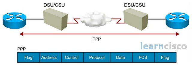
As a protocol, PPP originally emerged as an encapsulation method for transporting IP traffic over point-to-point links. It provides router-to-router and host-to-network connections over both synchronous and asynchronous circuits, for example, a leased line in case of synchronous and dial-up connections for asynchronous circuits. It is an enhancement over HDLC because it first of all provides link configuration, quality testing and error detection, but also additional capabilities like authentication, multilink bundles, and constant link monitoring.

In terms of the architecture and frame formats, PPP can be seen as three different sub-protocols, for framing and lower level capabilities; it is basically HDLC. If you see the frame formats, it is very similar to HDLC. One sub-layer above is LCP, which provides all of the additional functionality in terms of authentication, multilink, and the general establishment configuration and testing of the data link connection. A third protocol is NCP; it is used for establishing and configuring different network layer protocols. It is basically the interface toward the upper layers.
Just like any other encapsulation method, configuration is straightforward, going to the interface and using the encapsulation command to configure PPP. After this is done and PPP is working, you can add additional functionalities with commands like PPP authentication, PPP multilink, and others.
Router(config-if)#encapsulation ppp
PPP Configuration Example
The basic configuration though only requires the two sides to be configured with the same encapsulation method, this time PPP. A lot of times, though this protocol is used for on-demand type connections where users need to be authenticated or perhaps routers need to be authenticated, DSL continues to use PPP in the form of PPP over ATM or PPP over Ethernet. With those flavors, DSL connections and subscribers can be authenticated when connecting to the DSL network.
So now in this example, both router A and B are utilizing ppp encapsulation.

RouterA(config)#interface Serial 0/0/0
RouterA(config-if)#ip address 10.0.1.1 255.255.255.0
RouterA(config-if)#encapsulation PPP
RouterA(config-if)#bandwidth 512
RouterA(config-if)#clockrate 64000
RouterA(config-if)#no shutdown
RouterB(config)#interface Serial 0/0/0
RouterB(config-if)#ip address 10.0.1.2 255.255.255.0
RouterB(config-if)#encapsulation PPP
RouterB(config-if)#bandwidth 512
RouterB(config-if)#no shutdown
Whichever encapsulation method you select, you can verify the configuration using the show interfaces command.
Frame Relay
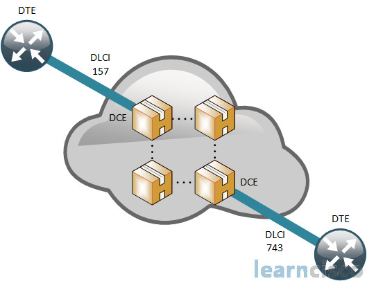
Frame relay is another example of a network that would connect to the router with a serial interface. In frame relay, though the encapsulation command, would indicate a frame relay encapsulation. Additional configurations would be required to define DCEs and DTEs at the frame relay level, also the DLCI (Data Link Connection Identifier) pointing to the virtual circuit across the frame relay network. Other options include the definition of the committed information rate (CIR) and the specification of quality of service parameters across the frame relay network.
Let’s take a more detailed look at virtual circuits on frame relay. A virtual circuit is nothing more than a logical connection between two DTEs. A DTE is the router on the client side. That logical connection can take multiple physical paths; in fact, service providers will create as much redundancy as they can in their provider network to allow for multiple paths for similar virtual circuits. You can terminate multiple virtual circuits on the client side.

The DLCI, or data link connection identifier, helps you understand which tunnel in which circuit you are entering from the same physical interface. In fact, DLCIs are layer 2 identifiers for all the steps of the path.
ATM and Cell Switching
Finally, ATM was in its heyday, the option of choice for transporting, voice, video, and data through private and public networks. It is a special case of a packet switch network also because it contains or defines fixed size cells instead of packets. The cells are 53 bytes in size and resulted in a new category of protocol called cell switching instead of packet switching. ATM is becoming less and less popular as a connectivity option toward the service provider and even within the service provider backbone in favor of other protocols like MPLS.
Our Recommended Premium CCNA Training Resources
These are the best CCNA training resources online:
Click Here to get the Cisco CCNA Gold Bootcamp, the most comprehensive and highest rated CCNA course online with a 4.8 star rating from over 30,000 public reviews. I recommend this as your primary study source to learn all the topics on the exam.

Want to take your practice tests to the next level? AlphaPreps purpose-built Cisco test engine has the largest question bank, adaptive questions, and advanced reporting which tells you exactly when you are ready to pass the real exam. Click here for your free trial.
